

 Brother Printers
 WhiteBoard


 IP PBXs






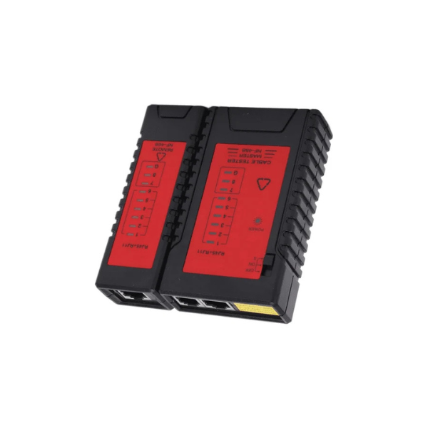
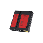

D-Link Cable Tester – Detected Cable – NTL-CT-001
Key Features
Brand: D-Link
LED Indicators: Full LED indication lights on both main and remote units
Connector Compatibility: RJ11, RJ45, BNC
Cable Types: Supports testing of Ethernet cables, telephone lines, and coaxial cables
Auto Test Feature: Yes, with an adjustable switch to slow down the testing speed
Power Supply: 9V battery (not included)
Dimensions: Approximately 105 x 68 x 28 mm
Weight: Approx. 150 grams (including battery)
1 Year Warranty
D-Link NTL-CT-001 Network Cable Tester: The Essential Field Tool for Flawless Connectivity Troubleshooting
Deploying professional networking infrastructure requires absolute accuracy at every termination point. The D-Link NTL-CT-001 Network Cable Tester provides a compact, portable, and trade-grade diagnostic solution designed specifically for IT professionals, structured cabling installers, and CCTV technicians. By offering instantaneous hardware verification for multiple data transmission lines, this tool removes the guesswork from field maintenance and guarantees baseline performance before network deployment.
Why Invest in the D-Link NTL-CT-001 Cable Tester
The D-Link NTL-CT-001 serves as a reliable field instrument to map, verify, and diagnose physical layer cabling architectures without adding complex software configurations.
Comprehensive Multi-Connector Support
Instead of carrying independent diagnostic equipment for various transmission standards, the NTL-CT-001 features built-in physical terminal beds built to safely test three crucial core communication paths:
-
- RJ45 Modular Jacks: For standard eight-conductor twisted-pair Ethernet cables (Cat5e, Cat6, Cat6a).
- RJ11 Modular Jacks: For telephone lines and voice-delivery structural wiring loops.
- BNC Interfaces: For coaxial lines, analog video connections, and high-density legacy CCTV setups.
Intelligent Two-Part Detachable Architecture
The physical chassis consists of a Master unit and a Remote terminator block that slot together cleanly for storage. For long-distance cabling or in-wall structured runs, the Remote terminator can be uncoupled and taken to opposite ends of a building—supporting data verification over runs up to 100 meters in length.
Auto-Scan Mode and Adjustable Speed Control
The operating framework relies on an automated line-stepping sequence that sweeps through connections effortlessly. The integrated control switch includes three physical logic levels:
-
- ON Mode: Runs a rapid sequential flash sequence across all pins for high-speed diagnostic sweeps.
- S (Slow) Mode: Deliberately slows the automation cycle, giving technicians clear visibility to map out cross-wired paths or flickering pins precisely.
- OFF Mode: Completely disconnects the internal battery source to extend your field toolkit’s standby life.
Pinout Diagnostic Interpretations
The NTL-CT-001 features dual matching LED indication strips (1 through 8, plus a Ground marker) on both the main and remote faces. When a cable is functioning perfectly under standard T568A or T568B wiring configurations, the lights illuminate in an identical, numerical sequence from 1 to 8 simultaneously on both units. Deviations reveal physical cable faults immediately:
-
- Open Circuit: If a specific light fails to illuminate on either panel, that targeted pin core contains a physical break or a loose crimp connection.
- Short Circuit: If multiple indicator lamps illuminate simultaneously on the remote receiver, the cable line contains an inner short circuit where exposed copper leads are touching.
- Crossed Wire: If the lights flash out of order on the remote terminal (e.g., 1-2-4-3-5…), the internal wire pairs have been crossed or incorrectly arranged during connector termination.
Technical Specifications Table
| Metric Feature | Specification Detail |
|---|---|
| Model Code | NTL-CT-001 |
| Interface Compatibility | RJ-45 (Ethernet), RJ-11 (Voice), BNC (Coaxial) |
| Maximum Cable Length | Up to 100 Meters (328 Feet) |
| Diagnostic Elements | Continuity, Open Lines, Shorts, Crossed Pairs |
| Operational Modes | Fast Scan, Slow Scan (S), Off |
| Display Panel Type | Dual LED Status Indication Indicators |
| Power Profile Source | 1 x 9V Alkaline Battery (Excluded) |
| Device Measurements | Approximately 104 mm x 96 mm x 27 mm |
Frequently Asked Questions (FAQs)
Can I safely plug an active PoE line into the NTL-CT-001?
While the tester can handle standard network testing configurations, you must ensure that lines carrying high-voltage active currents from a PoE switch or injector are disconnected before testing. Introducing raw electrical voltage above 60V DC into basic continuity testers can easily damage the sensitive internal LED sensing components.
Why are the lights flashing out of sequence on my custom-built patch cord?
If the LEDs flash out of order on the remote unit compared to the main unit, it indicates a miswire or crossed pair fault. This means the inner color-coded wires were loaded into the modular plug incorrectly before crimping. You will need to cut off the connector and re-terminate the wire using a reliable crimping tool.